Air Data Sensors
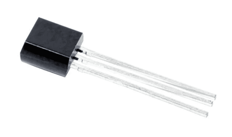
Temperature sensor LM335

LM335 sensor
The LM335 is an analogical temperature sensor that measures temperatures from -40°C to 100°C.
It changes the voltage according to the temperature measured and therefore the connection to the autopilot is performed using the ADC pins.
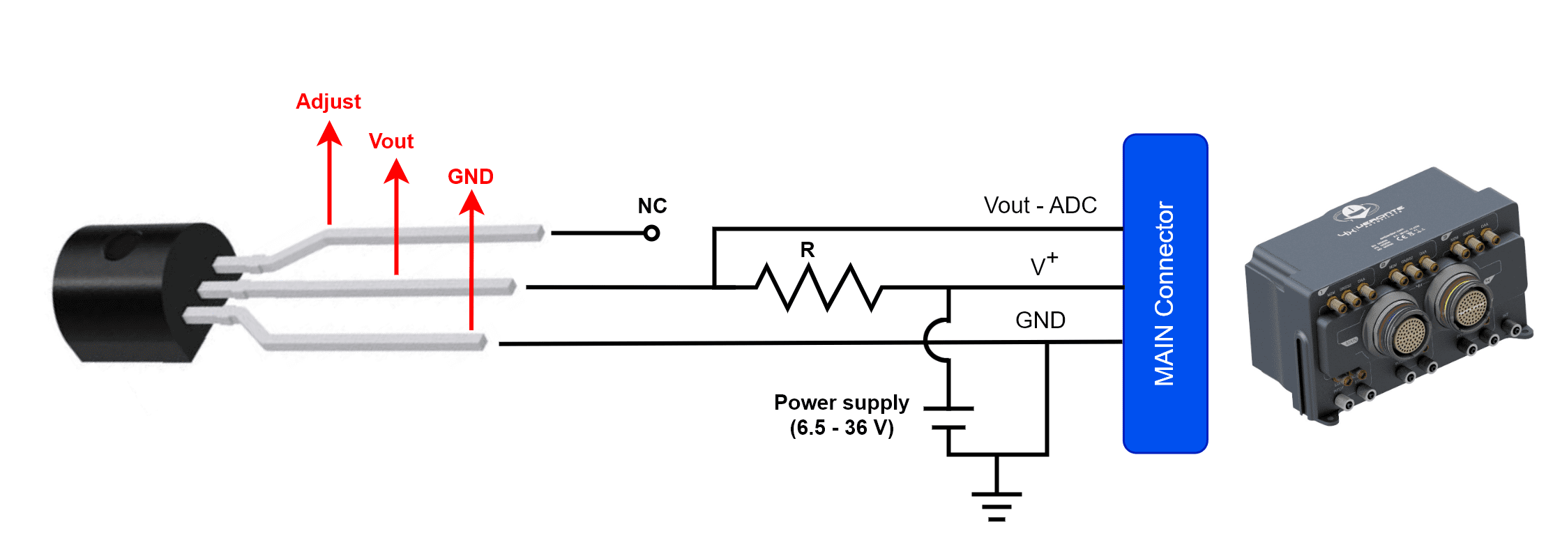
The following wiring is necessary to connect a sensor to the autopilot:

LM335 sensor - 4x wiring diagram
The LM335 sensor can share voltage supply with the Autopilot 4x. However, the impedance of the resistor R must vary with the voltage; since the sensor requires a forward current between 0.4 and 5 mA to operate. We recommend to use a resistor as high as possible complying with the folllowing equation:
Where R is the value of the resistor (ohms) and Vin is the supply voltage (V). The following table shows a list of examples of a tested resistor for each voltage supply. Obtaining an error average of 1.5 °C.
Vin (V) |
R (kohms) |
|---|---|
6.5 |
5 |
12 |
16 |
24 |
37 |
36 |
60 |
The Vout pin has to be connected to an analog input of the Main connector.

Main connector harness pinout
Users must choose one analog pin to connect:
Main connector harness
LM335 sensor
PIN
Signal
Color code
Signal
22
ANALOG_3
Brown - Blue
Vout
23
ANALOG_4
White - Red
38
ANALOG_0
Red
39
ANALOG_1
Black
40
ANALOG_2
Violet
Users must use the supply voltage according to the Autopilot 1x being used:
Main connector harness
LM335 sensor
PIN
Signal
Color code
Signal
64
BAT_2
Yellow
V+
67
BAT_1
Blue
68
BAT_0
Red
Users must choose one ground pin to use:
Main connector harness
LM335 sensor
PIN
Signal
Color code
Signal
9
GND
Black
GND
18
Gray - Brown
27
Gray - Green
33
Green
41
Gray - Pink
44
Brown - Green
47
White - Gray
48
Gray - Brown
59
Pink - Green
63
Green
65
Gray
66
Pink
Once connected, the temperature can be monitored in 1x PDI Builder by using the variables ADC0 to ADC4. The wiring explained previously obtains a relationship of Temperature and Vout as follows:
Where T is the measured temperature (in °C, since 273 is substracted in the formula) and Vout the output voltage of the previous circuit.
The integration of this device with Autopilot 4x is explained in the LM335 with Autopilot 4x - Integration examples section of the 1x PDI Builder manual.
